OUTLINE:
A Beginner's Guide to LCR Meter
 208
208What is a LCR Meter
An LCR meter (Inductance (l), Capacitance (C), and Resistance (R)) is a tool for measuring the inductance, capacitance, and resistance of a component, sensor, or other device whose operation is dependent on capacitance, inductance, or resistance.
LCR meter can accurately and stably measure various component parameters, mainly used to test inductance, capacitance and resistance. It has the characteristics of direct function and easy operation, and can meet the testing requirements of production line quality assurance, incoming inspection, electronic maintenance and other industries with a low budget.
Capacitors and inductors are reactive components, which means their values vary with frequency. An LCR meter measures these shifts precisely using a tiny AC signal.
Frequency: Common settings include 100 Hz, 120 Hz, 1 kHz, 10 kHz, and higher.
Test Voltage: Typically around 1 Volt RMS or lower, which is crucial for accurate measurement.
The device uses these inputs to determine key properties by analyzing voltage and current waveforms.
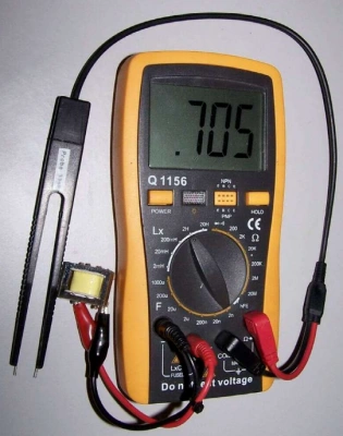
Meaning of LCR Meter Parameter
LCR meters are widely used because of their straightforward functions and easy-to-operate test methods.
They are usually used to accurately test the parameters of various components, and the effect is very stable, thereby ensuring production quality and saving corporate costs. D and Q are often displayed. However, many people do not know what this means. There are also LP and LS in the parameters of meters, and they don’t know what the difference is.
The D displayed on the LCR meter is the loss tangent, and Q is the quality factor. The definitions of these two quantities are as follows: 1. Loss tangent: If a voltage is applied to a capacitor, in addition to the current charged into the capacitor, there is also a leakage current (leakage current of the capacitor). The leakage current is consumed in the form of heat energy, so it is expressed as a current on the resistor. The ratio of the leakage current of a pure capacitor to the charging current is the tangent of the capacitor loss angle.
2. Quality factor: the quantity of electricity and magnetism. A quality indicator that represents the ratio of energy stored in energy storage devices (such as inductors, capacitors, etc.) and resonant circuits to energy loss per cycle; the Q value of a reactive element in a series resonant circuit is equal to the ratio of its reactance to its equivalent series resistance; the greater the Q value of a component, the better the selectivity of the circuit or network composed of the component. The inductance, capacitance, and resistance parameter measuring instrument in the LCR meter can not only automatically determine the properties of the component, but also display symbol graphics and display its value. It can also measure parameters such as Q, D, Z, Lp, Ls, Cp, Cs, Kp, Ks, and display equivalent circuit graphics.
Types of LCR Meters
Handheld Models
- Portable, affordable, and great for fieldwork.
- Example: The Tenma model used in the video costs around $175.
Bench Models
- Higher precision and more features like frequency sweeps and impedance plots.
- Suitable for advanced circuit design and research.
Impedance Analyzers
- High-end tools for professional labs, capable of detailed frequency-response analysis.
Key Features of an LCR Meter
Let’s take a closer look at the capabilities of an LCR tester:
A. Modes of Measurement
Capacitance (C): Measures the ability of a capacitor to store charge.
Inductance (L): Measures the ability of an inductor to generate magnetic fields.
Resistance (R): Measures resistance in both DC and AC forms.
Secondary Parameters: Includes ESR, quality factor (Q), dissipation factor (DF), and phase angle.
B. Adjustable Frequency
Many meters allow you to select the test frequency (e.g., 100 Hz, 1 kHz, 10 kHz) to match the operating conditions of the component or circuit.
C. Calibration Options
Most LCR meters include calibration modes to compensate for errors introduced by test leads or probe setups.
D. Series vs. Parallel Mode
Determines how resistance is treated:
Series Mode: Best for large capacitors or small inductors.
Parallel Mode: Best for small capacitors or large inductors.
Principle of LCR Meter
The working principle of the LCR tester is based on the characteristics of the AC circuit. It uses a sine wave signal as a test signal and calculates electrical parameters by measuring the relationship between current and voltage.
Test principle of balanced LCR tester: Zx=Vx/lx=Rr*Vx/Vr, that is, by measuring the voltage and current loaded to the DUT, the DUT impedance value can be measured.
As can be seen from the figure below, the current through the DUT is equal to the current through the resistor Rr, and the current through Rr can be calculated by measuring Vr.
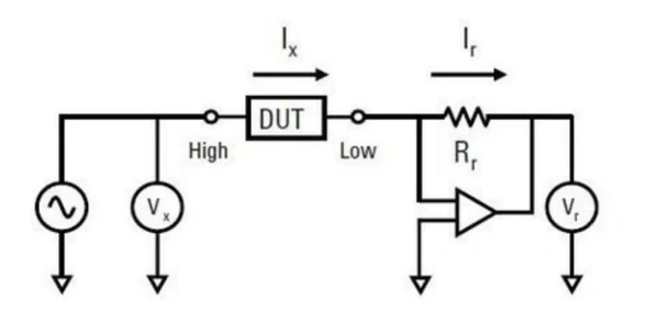
How to measure resistance using an LCR meter
Step 1: Discharge the Component
Before connecting a capacitor, discharge it to avoid damaging the meter. The process of discharging a capacitor involves the safe releasing of its stored energy for the elimination of any dangers involved.
Detailed steps >> How To Discharge A Capacitor
Step 2: Connect the Component
Choose the appropriate connection method based on the type of component:
Surface Mount Components: Use tweezers with shielded leads for precise readings.
Through-Hole Components: Use a clip adapter or mini grabbers.
Step 3: Calibrate the Meter
Perform open and short calibrations to eliminate the influence of test leads or probes.
For open calibration: Leave probes disconnected.
For short calibration: Short the probe tips using a metal conductor.
Step 4: Select Measurement Mode
Use Capacitance Mode for capacitors, Inductance Mode for inductors, and so on.
Adjust the frequency to match the circuit conditions or the component’s datasheet specifications.
Step 5: Take Measurements
Insert the component and note the displayed values.
The meter may also display secondary parameters like ESR, dissipation factor, or phase angle, depending on the mode.
Step 6: Interpret the Results
Use the frequency response data to verify the component’s suitability for the intended application. For example:
A capacitor's ESR might increase at higher frequencies, making it unsuitable for certain circuits.
Instrument Selection
Test Frequency
Electronic components need to be tested at the frequency used by the finished product or application.
The test frequency must be consistent with the operating frequency of the object under test.
Test Voltage
Most LCR testers can select the signal level applied to the object under test.
Typically, this test signal voltage is measured under open circuit conditions.
Accuracy/Speed
The test speed of the LCR tester is inversely proportional to the test accuracy. The longer the test time, the higher the test accuracy; conversely, the faster the test speed, the lower the test accuracy.
Measurement Parameters
Main parameters L, C and R; secondary parameters D, Q and θ.
Range
In order to measure a wide range of impedance values, the test instrument must have multiple selection ranges. The range is usually automatically selected according to the impedance value of the object under test.
Average value
The average value is related to the integration time of the LCR meter. If the integration time is greater than the test signal period, the measurement time will be longer, but the accuracy will be improved.
Bias voltage and bias current
Some LCR meters include bias voltage or bias current functions.
Wide measurement frequency
Hundreds of test frequencies can be selected for different applications; some products can select continuous frequency points.
Absolute value, △ value display
Some instruments can select three measurement display modes for different test conditions.
Difference between LCR meter and multimeter
Unlike a Digital Multimeter (DMM), LCR meter measures AC impedance, including parameters like dissipation factor, ESR (Equivalent Series Resistance), and others.
DMM: Measures basic properties like resistance, DC voltage, and current. Some models include capacitance measurement but with limited accuracy.
LCR Meter: Goes beyond capacitance and resistance to measure parameters such as reactance, impedance, ESR (Equivalent Series Resistance), dissipation factor, and more.

Disclaimer: The views and opinions expressed by individual authors or forum participants on this website do not represent the views and opinions of Chipsmall, nor do they represent Chipsmall's official policy.

share this blog to:
Relevant Parts for Sale
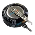
EECS0HD224V
CAPACITOR, ELECTRIC DOUBLE LAYER, 5.5V, 220000uF, THROUGH HOLE MOUNT, ROHS COMPLIANT
