OUTLINE:
The Inductor Symbol: A Crucial Part of Circuit Design
 274
274When it comes to electronic engineering, people are amazed at its complexity. This is because simply understanding electronic components requires a significant investment of time and energy. Different electronic components have their own features and characteristics, and are an essential part of the development process of modern electronic technology. One of the most common electronic components is the inductor. As an electronic component capable of converting electrical energy into magnetic energy and storing it, it is primarily used to change the size and direction of the current, as well as the frequency and resistance in the circuit, allowing electronic circuits to perform a wide range of functions. As a result, even if the technicians have discovered the physical principle and existence of the inductor, they must additionally utilize a tool to materialize the inductor in order to have a deeper understanding of it. At this time, the inductor symbol was created, and its manufacturing is similar to a bridge, allowing engineers to investigate inductors while also improving work efficiency. Based on this, this article will guide readers into the hidden realm of the inductor symbol, revealing the mystery behind it and exploring its distinct appeal and significance in electronic engineering design.
A Brief Introduction to Inductors
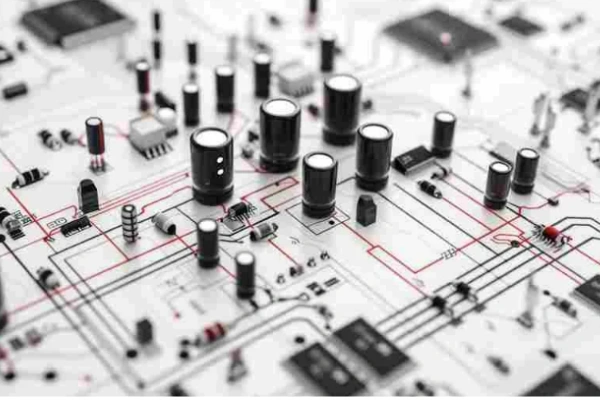
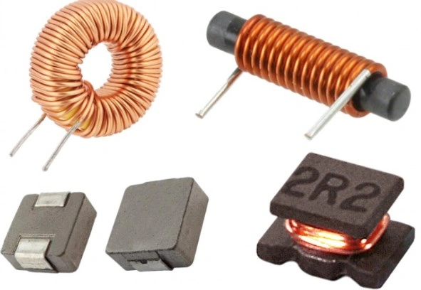
Inductor is a type of passive electronic component that can store magnetic field energy. Simply put, an inductor is a coil, and our most common inductor is a wire wrapped around the insulation skeleton to form one or more coils; these coils generate a magnetic field when current passes through, and then store and release energy. The main feature of the inductors is to block the current change. In addition to storing energy, the inductor can operate as a filter, transformer, impedance current, oscillation, and so on. Now, you probably still don't comprehend these effects, which is understandable because these theories sound a little esoteric to amateurs, but don't worry, I'll give you a quick overview. The first is function one, which uses the inductor as a filter. Because inductors can block high-frequency signals while allowing low-frequency signals to flow through, this characteristic makes inductors very suitable for use as filters in power and signal processing, inductors and capacitors can effectively filter out the specific frequency components of AC signals, retaining or transmitting the required signal.
Then there is the instance where the inductor is employed as a transformer. According to the description of the notion of inductors, when current flows through an inductor, a magnetic field forms around it. This magnetic field changes as the current changes, resulting in a self-induced electromotive force within the inductor that prevents the current from changing. If you want the inductor to perform the role of a transformer, you will need another inductor to assist. Magnetic coupling connects two inductors with varying numbers of coils. When the current in the first inductor changes, a changing magnetic field is formed around it. Magnetic coupling connects two inductors with differing numbers of coils, and when the current in the first inductor varies, a changing magnetic field is formed around it, resulting in induced electromotive force in the other inductor. Because the number of turns in the two inductors differs, the amplitude of the output voltage varies, and the voltage transformation is accomplished using this concept.
Inductors can also be used to impede current and act as oscillators. When inductors are employed in pairs in a transformer, electromagnetic induction transfers energy between the two circuits, allowing technicians to increase or decrease the voltage in circuit design based on actual needs. Inductors are paired with capacitors in radio transmitters, signal generators, and other types of electronic communication systems, resulting in an LC circuit that generates an oscillating signal, constituting an oscillator.
As can be seen from the above quick introduction to inductors, inductors are a critical electronic component in the field of electronics, which is why an amateur should grasp inductors before joining the field of electronic and electrical engineering.
What is an Inductor Symbol?
When discussing inductors, you must mention the inductor symbol. Because of the widespread use of inductors, engineers and technicians cannot take an inductor to the site to explain circuit operation, and most importantly, before practicing, engineers and technicians must design the circuit diagram. As a result, people must consider the following problem: how to express the inductor on the circuit diagram? In fact, whether it is an inductor or an inductor symbol, they are inseparable from the development and formation of early electromagnetic theory. When the inductor is gradually accepted by people, scientists in order to represent the position of the inductor in the circuit diagram, they draw the inductor into a symbol: A series of rings or semicircles (indicating connections from one end to the other), and the inductor. The appearance of the inductor symbol not only confirms the widespread use of inductors, but also improves the work efficiency of engineers and technicians, allowing everyone who sees the circuit diagram to immediately and clearly know: "Oh, the original symbol drawn in this position represents the inductor!"
Type of Inductor Symbol
Although the inductor symbol is widely recognized, there is not only a single type of inductor, so there are different categories of inductor symbols, these classifications can play a role in communicating other information about the characteristics of different inductors, with them, technicians can judge from the simple situation when encountering problems, without the need to examine the circuit in depth. Therefore, this section will introduce you to the types of inductor symbols.
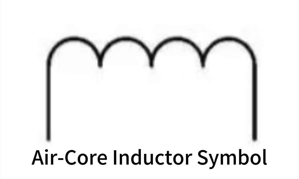
In general, inductor symbols include six types: Air-Core Inductor Symbol, Iron-Core Inductor Symbol, Ferrite-Core Inductor Symbol, Tapped Inductor Symbol, Variable Inductor Symbol, Coupled Inductor Symbol.
The Air-Core Inductor Symbol is the most basic inductor symbol. It usually uses one or more concentric circles, ellipses or wavy lines to represent the coil, and the letter "L" is marked next to it to represent the inductor. The expression of this symbol is based on the characteristics of the inductor. The air-core inductor symbol represents a coil without any magnetic core, so it is also the easiest to identify and draw. Air-core inductors are often used where minimal magnetic losses are required, such as in high-frequency applications.
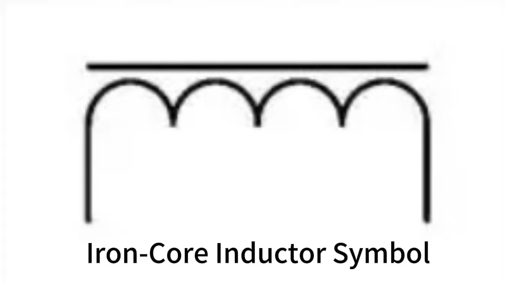
The second type of inductor symbol is the Iron-Core Inductor Symbol, and its graphical representation is usually to draw a coil first, and the existence of an iron core is expressed inside or next to the coil in some way, which can not only distinguish the core inductor symbol from the basic inductor symbol, but also help highlight the characteristics of the core inductor. It should be noted that in real life, if you look carefully, you will find that the iron-core inductor symbol is usually represented by adding a straight line to the empty core inductor symbol, which will fall parallel to the standard inductor symbol above. In electrical engineering, iron-core inductors are often used as power supplies and transformers.
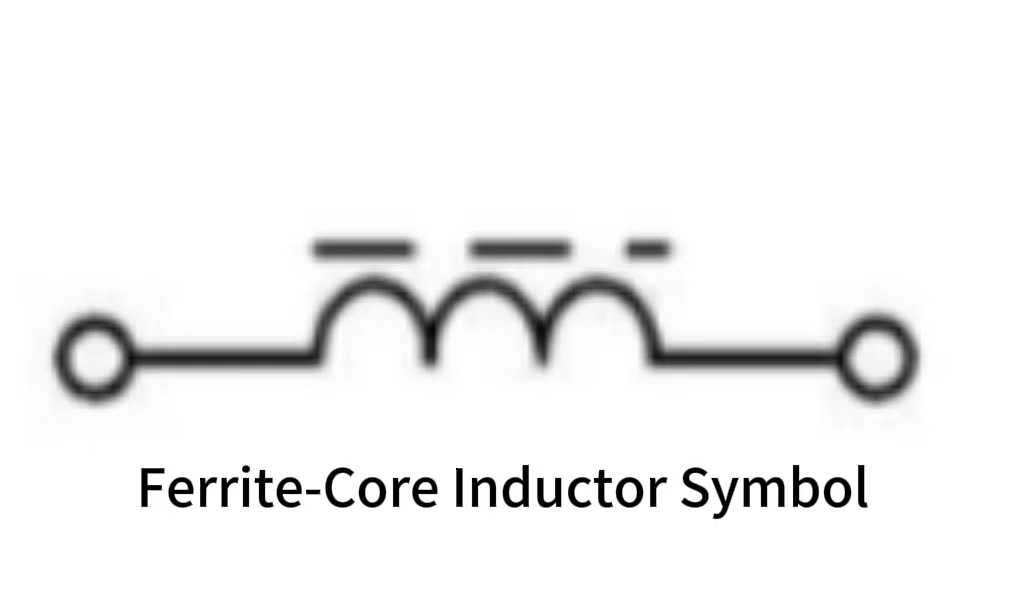
Similar to the iron-core inductor, there is also a symbol named Ferrite-Core Inductor Symbol. Ferrite-core inductors are often used in high frequency applications, such as radio frequency circuits, due to their ability to provide high inductance and low loss. In addition to similar names, the ferrite-core inductor symbol and the core inductor symbol are also very similar in their representation. The ferrite-core inductor symbol includes parallel lines, but with a dashed or dashed line pattern.
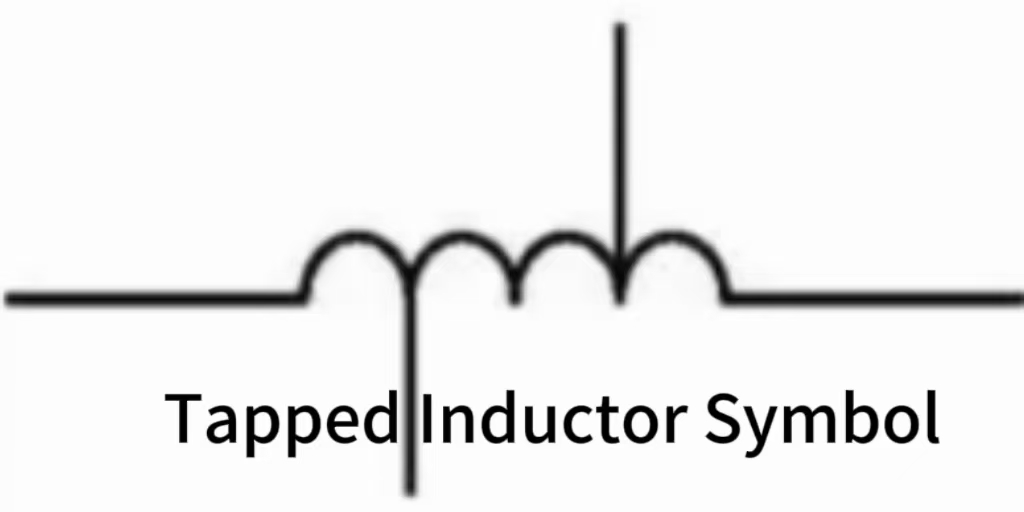
The fourth type of inductor symbol is the tapped inductor symbol, which is a special type of inductor element, and its distinctive feature is that one or more lead wires are provided on its winding, thus allowing the realization of multiple current access points. As a result, while representing the inductor symbol, the focus can be on characterizing its lead line. Tapped inductor symbols consist mostly of three elements: standard inductor symbols, lead lines, and numbers, letters, or other marks. The tap inductor symbol can be drawn using the normal inductor symbol, which is a coil, with one or more lead lines added to symbolize the tap. These leads can be drawn from various spots in the coil to represent different tap sites. To better express the position and amount of taps, the graphic symbol may include a number or letter marker. Tapped inductors are most commonly employed in power filters, electronic tuners, frequency converters, and industrial automation.
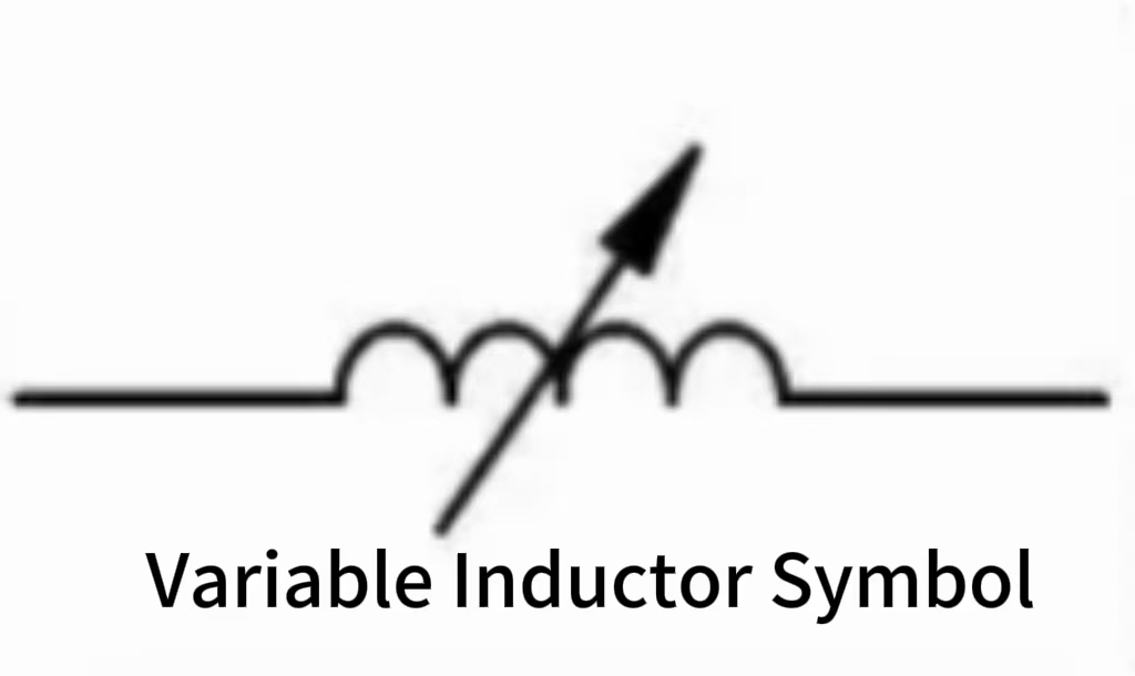
The fifth is the variable inductor symbol, this symbol represents an inductor that can adjust the inductor value data, the most special place of this inductor symbol is that the graphic symbols drawn by engineers in different countries may not be consistent. In simple terms, this is because the variable inductor symbol first draws a basic coil shape, and then there will be some special marks in the symbol, these special marks indicate that the inductance value can be adjusted, and these marks may be arrows, or it may be a graphical symbol indicating rotation. In addition, in some cases, the plotter will attach a text description next to the graphic symbol, such as "VARIABLE INDUCTOR", etc., in order to make it more clear that the symbol represents the variable inductor.
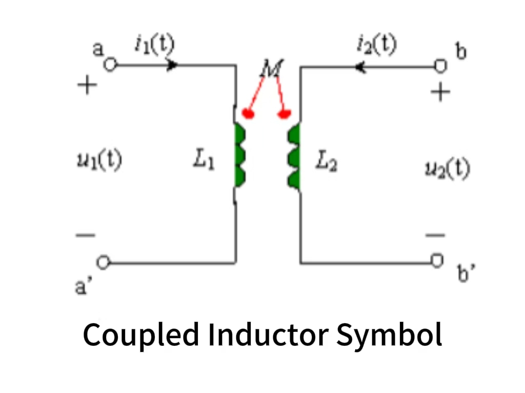
The last thing to discuss is the coupling inductance symbol. The characteristic of this inductor is that it contains two or more coils, and its corresponding symbol is thus reflected. The working principle of coupled inductors is based on the fact that a change in current in one coil will create a changing magnetic field, which in turn affects the other coils, resulting in an induced electromotive force. The memory method of coupling inductance symbols is relatively simple. When drawing, two standard inductance symbols can be placed side by side and then connected with a line or a point to represent the magnetic field coupling. The coupled inductance symbol has high practical value in the fields of power transmission and signal separation.
The above are several common inductor symbols. If you are interested in this, I strongly recommend that you try to draw these symbols yourself based on the descriptions of these inductor symbols in the article. This will not only deepen your impression of inductor symbols, but also help you in your future work.
The applications of the Inductor Symbol
The inductor symbol appears to be a simple graphic, but it is an essential tool in the field of electronic engineering. As a result, in addition to comprehending the inductor symbols and the inductors associated with each symbol, one must also understand which inductor symbols will be utilizing which situations. Therefore, this section of the essay will provide you with a brief introduction to the meaning of the inductor symbol as well as practical applications of the situation. If you are a beginner in electronic engineering, I hope you find this information useful.
The most important role of the inductor symbol is, of course, the application in the field of circuit design, a standard circuit diagram, not only requires that the circuit drawing is completely correct, but also requires that the various inductor symbols used in the diagram must be correct, otherwise it will not be able to become an accurate circuit diagram. Therefore, in the process of circuit design requiring high precision and high accuracy, accurately describing the inductor symbol is a key step. In addition, the inductor symbol can also reflect the key performance parameters of the inductor. For example, inductance is represented by the letter "L", reflecting the role of the inductor in storing and releasing energy; The letter "Q" represents the energy loss of the inductor when resonant, recalling the above mentioned below, some inductor symbols need to mark letters or numbers next to the graph, probably because the key performance parameters of different types of inductors will be different. Therefore, although the expression of the inductor symbol is simple, if it is applied to real life, there are still many places that need attention.
Secondly, in the process of manufacturing and assembling electronic devices, inductor symbols also play an important role. In the manufacture of electronic devices, electronic engineers need to draw the circuit diagram first, the drawn circuit diagram is like a manual, the technician according to this manual assembles the components, ensures that the correct inductor components are used and finally installed on the product. In addition, if a specific inductor needs to be used as a single device in the process of manufacturing an electronic product to be used, the inductor symbol can play a role in distinguishing types and reducing errors in work.
Once an electronic circuit is designed or developed, it is not immediately put into use. Engineers also need to simulate and test the electronic circuit. The so-called "simulation and testing" is to simulate the direction of the circuit and analyze the feasibility, so as to save time and resources, because if an untested circuit is put into use, if there is a problem, the consequences will be unimaginable. The inductance symbol is also a tool that cannot be ignored in this process. When engineers use simulation software, the inductance symbol will be used as a bridge to transmit inductance information. When the detailed information of inductance in the circuit crosses the bridge and is recorded by engineers, engineers will use this information to simulate the direction of the inductor in the circuit to ensure that the designed circuit has no deviation. If there is a deviation in the circuit, engineers can also exclude the inductor one by one, and make a mark in the circuit diagram after checking. It can be seen that in circuit design, the inductor symbol can greatly improve the work efficiency.
To sum up, although the inductor symbol is often not a thing that people pay attention to, in fact, its role is far beyond our imagination, therefore, in learning and understanding the knowledge in the field of electronic engineering, we must not ignore the learning of the inductor symbol.
How to Understand Inductor Symbols in Circuit Diagrams?
If you are an amateur in the field of electrical engineering, I think in addition to understanding the basics, you also need to know how to understand the inductor symbol in the circuit diagram, because if you do not understand the inductor symbol in the circuit diagram, even if you learn all the theoretical knowledge, you will not be able to practice in the field of electrical engineering. Hopefully, after following these steps, your accuracy in judging the inductor symbol of a circuit diagram will be greatly increased.
In order to understand a circuit diagram, the first step is to carefully look for the diagram drawn as a semi-circular arc or ring sequence of figures; these figures are standard inductor symbols, usually representing inductance. Of course, you also need to pay extra attention to whether there are other marks or comments around these figures, if there are, then you need to understand what these marks represent, because different types of inductors draw inductor symbols are not the same. Then, you need to analyze what role the inductor plays in a circuit, or what type of inductor is used in the circuit, at the same time, you also need to observe the inductor connection in the circuit, and the relationship between the surrounding components, etc., because these will be related to your understanding of the inductor symbol when reading a circuit diagram.
Development Trend of Inductor Symbols in Circuit Design
With the development of the electronics field, the inductance symbol may also change in the future. Before the unified inductor symbol was created, engineers may directly draw the inductor symbol, which increases the difficulty of the work, and as the inductor enters the public vision and is widely recognized, the standard drawing of the inductor symbol has been unified all over the world. As a person who studies inductors or electronics, we may wish to expand our imagination and boldly imagine the development trend of inductor symbols in the future.
First of all, in the field of circuit design, the inductor symbol still occupies an important position, as mentioned above, due to the different words used in different countries, the expression of the inductor symbol will be different, and even because of the language and the learning of the inductor knowledge will be hindered, but the symbol is a common understanding of people all over the world. In the future, the expression of inductor symbols or graphics may develop due to changes in science and technology, and may become simpler, so that everyone can identify the symbol graphics of different types of inductors at a glance. In addition, the emergence of AR and VR may change the way the circuit diagram is drawn, in which case the inductor symbol and other electronic symbols will become visualized, and it may even occur that "engineers search for the inductor required by the circuit diagram, the inductor in 3D space will recognize the type of inductor and automatically generate the inductor symbol". With the support of highly developed technology, both engineers and people who need to learn the knowledge of inductors can easily draw a standard circuit diagram.
The End
Through the understanding of the inductor symbol, I believe that readers no longer just regard the inductor symbol as an insignificant graphic symbol on the circuit diagram. Indeed, the inductor symbol is like a "bridge", whether you are a student, engineer or amateur enthusiast studying electronic engineering knowledge, understanding the inductor symbol is an indispensable step in the basic stage, only when learning knowledge to build a "bridge" firmly, you can more smoothly complete the rest of the electronic field of knowledge learning. Of course, if you are an imaginative electronic engineering practitioner, you can also use your professional advantages to boldly imagine the future development trend of inductor symbols in the professional field, for example, with the development of science and technology, will inductor symbols remain unchanged in the future? If not, what form will it take? I hope you will learn something new and inspired after reading this article.
Disclaimer: The views and opinions expressed by individual authors or forum participants on this website do not represent the views and opinions of Chipsmall, nor do they represent Chipsmall's official policy.

share this blog to: