OUTLINE:
What Are Noise Filtering Circuits
 172
172In electronic systems, noise often manifests as unwanted electromagnetic interference or signal fluctuations, which can superimpose on useful signals, resulting in signal distortion, degraded device performance, and even system failure. It can come from a variety of sources, such as AC noise from the power line, electromagnetic interference in space, or mutual interference between components inside the device. Therefore, noise filtering circuits are specially designed to filter out the noise signal to solve these problems.
Basic concept of noise filtering circuits
Noise has different characteristics, according to the frequency distribution can be divided into white noise and colored noise. White noise has a uniform power spectral density over the entire frequency range, just as white light contains all colors of light, its energy distribution is more average at each frequency. The power spectral density of colored noise varies with frequency, for example, the 1/f noise (flicker noise) with the larger power of low-band noise is colored noise. Noise can also be divided into additive noise and multiplicative noise according to its relationship to the signal. Additive noise is independent of the signal and directly superimposed on the signal. Multiplicative noise multiplies the signal, usually changing the amplitude and phase of the signal.
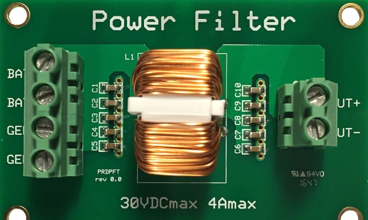
Filtering is a process of extracting the desired signal from the mixed signal while suppressing the unwanted noise. In the field of electronics, filtering is usually implemented through a specific circuit structure. The core idea of noise filtering circuit is to selectively process signals of different frequencies by using different characteristics of signals in circuit components (such as resistors, capacitors, inductors, etc.). For example, capacitors have a lower impedance to high-frequency signals and a higher impedance to low-frequency signals; Inductors, on the other hand, have a lower impedance to low-frequency signals and a higher impedance to high-frequency signals. By combining these components properly, we can build circuits that allow signals in a certain frequency range to pass smoothly, while attenuating noise at other frequencies.
Common types of noise filtering circuits
In this section, some common types of these circuits will be illustrated for your reference.
1. RC filtering circuit
There are mainly three types of RC filtering circuits.
For the first type, RC low-pass filtering circuit, is one of the most basic filtering circuits. Its structure is simple, consisting of a resistor R and a capacitor C in series, and the output signal is taken from both ends of the capacitor. RC low-pass filtering circuit is often used in audio processing, such as removing high-frequency noise from audio signals to make the sound more pure; In the power supply circuit, it can also be used to filter out the high-frequency ripple in the power supply and provide a stable DC voltage for electronic devices.
For the second type, in contrast to the low-pass filtering circuit, the output signal of the RC high-pass filtering circuit is taken from both ends of the resistor. In the high-pass filtering circuit, the capacitor presents a high impedance to the low-frequency signal, preventing the low-frequency signal from passing, and a low impedance to the high-frequency signal, allowing the high-frequency signal to pass smoothly. High-pass filtering circuits are often used in communication systems, such as in RF signal processing, to remove low-frequency interference signals and only let high-frequency RF signals pass through to ensure accurate signal transmission; In image signal processing, it can also be used to enhance the high frequency detail information of the image.
The last one is called bandpass filtering circuit. The RC bandpass filtering circuit can be implemented by cascading the low-pass filter circuit and the high-pass filter circuit. It allows signals within a specific frequency range to pass, while attenuating signals outside that range. Specifically, the low-frequency noise is first removed by a high-pass filtering circuit, and then the high-frequency noise is removed by a low-pass filtering circuit, so that the signal in the desired frequency range is obtained.
2. LC filtering circuit
The LC low-pass filter circuit consists of an inductor L and a capacitor C, usually the inductor is in series in the circuit and the capacitor is in parallel in the circuit. The inductor presents a high impedance to the high frequency signal, and the capacitor presents a low impedance to the high frequency signal, so the high frequency noise will be blocked by the inductor and will be bypassed to the ground by the capacitor, so as to achieve the filtering of the high frequency noise. Compared with RC low-pass filter circuit, LC low-pass filter circuit has better filtering effect in high frequency band, because the combination of inductor and capacitor can suppress high-frequency noise more effectively. It is often used in high-frequency circuits, such as RF front-end circuits, to filter RF signals, remove high-frequency stray signals, and improve signal quality.
Similarly, the structure of the LC high-pass filtering circuit is the opposite of the low-pass one. The capacitor is in series, and the inductor is in parallel in the circuit. The capacitor presents a high impedance to the low-frequency signal, and the inductor presents a low impedance to the low-frequency signal, and the low-frequency noise will be blocked by the capacitor and will be bypassed to the ground through the inductor, so as to achieve the filtering of the low-frequency noise.
And LC bandpass filtering circuits can be implemented in a variety of ways, the most common being series resonant or parallel resonant circuits. LC bandpass filtering circuit has important applications in communication and radar, such as in wireless communication systems, used to select a specific frequency band signal, to achieve the isolation between different channels and the accurate reception and transmission of signals.
3. Active filtering circuit
For an active filtering circuit composed of an operational amplifier, it usually consists of an operational amplifier and RC or LC elements. Operational amplifiers have the advantages of high gain, high input impedance and low output impedance, which can amplify weak signals and improve the performance of filtering circuits. The gain and frequency response characteristics of the filtering circuit can be adjusted by designing the feedback network of the operational amplifier reasonably. Compared with passive RC low-pass filtering circuit, active low-pass filtering circuits have better filtering effect and load capacity, and can meet higher performance requirements in different applications.
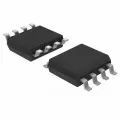
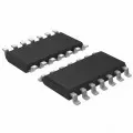
With the development of integrated circuit technology, many integrated active filtering chips have appeared. These chips integrate multiple operational amplifiers and related filtering elements in one chip, which has the advantages of small size, stable performance and easy use.
Working principle of noise filtering circuits
The working principle of noise filtering circuits is based on electromagnetism and circuit theory, which usually uses capacitors, inductors, resistors to form a specific circuit structure, by selecting appropriate component values and circuit topology, to achieve attenuation or suppression of noise signals in a specific frequency range.
Noise filtering circuit is mainly based on the response difference of circuit elements to different frequency signals to realize the filtering function. Take the most common RC filter circuit as an example, which consists of a resistor (R) and a capacitor (C). When a mixed signal containing multiple frequency components is input, the capacitor will shunt the signal of different frequencies according to its capacitive and reactance characteristics. For the high frequency signal, the capacitance reactance is small, most of the high frequency current will flow to the ground through the capacitor, so that the high frequency component of the output signal is attenuated; For the low-frequency signal, the capacitive reactance is large, the current flows mainly through the resistor to the output, and the low-frequency signal is relatively intact. In this way, after the RC filter circuit, the high-frequency noise in the output signal is effectively suppressed, and the low-frequency useful signal passes smoothly, realizing the purpose of filtering.
Similarly, the LC filtering circuit consists of an inductor (L) and a capacitor (C). The inductor presents a high impedance to the high frequency signal, and the capacitor presents a low impedance to the high frequency signal. In the LC filtering circuit, the high-frequency noise will be blocked by the inductor, and part of the high-frequency noise will be bypassed by the capacitor to the ground, which greatly reduces the high-frequency noise component in the output signal. For the low-frequency signal, the inductive reactance of the inductor is small, the capacitive reactance is large, and the low-frequency signal can successfully reach the output end through the circuit. This selective processing of different frequency signals based on circuit elements is the basic working principle of noise filtering circuit to achieve filtering function.
|
Working principle |
|
|
Capacitor filtering circuit |
The capacitor has the characteristics of "AC, DC". In noise filtering circuits, capacitors are often used to bypass high-frequency noise signals. When the frequency of the noise signal is higher than the cutoff frequency of the capacitor, the capacitor will present a very low impedance, which allows the noise signal to pass through and flow to the ground wire to achieve the purpose of filtering noise. |
|
Inductor filtering circuit |
In contrast to capacitors, inductors have the characteristics of "passing DC, blocking AC". Inductors are often used to suppress low frequency noise signals in noise filtering circuits. When the frequency of the noisy signal is lower than the cutoff frequency of the inductor, the inductor will exhibit a high impedance, which prevents the noisy signal from passing through. |
|
LC filtering circuit |
LC filter circuit is composed of a capacitor and an inductor. It combines the advantages of capacitors and inductors, and can effectively filter out noisy signals in a wider frequency range. There are various types of LC filter circuits, including low-pass filters, high-pass filters, band-pass filters and band-stop filters, and the appropriate type can be selected according to the actual needs. |
|
Active filtering circuit |
An active filtering circuit contains an amplifier, which achieves a larger attenuation of the noise signal. At the same time, this type of circuit also has better frequency selectivity and stability, which is suitable for occasions with high noise suppression requirements. |
Actual application of noise filtering circuits
Noise filtering circuits have a wide range of applications, covering almost all the fields that need to process electronic signals.
To begin with, in audio equipment, these circuits are used to filter out high-frequency noise and low-frequency hum in power lines and signal lines to ensure the purity and clarity of audio signals. Whether it is home audio, professional recording studio or live performance equipment, noise filtering circuits are an integral part of the process.
Moreover, in the communication system, the noise filtering circuits are used to suppress the electromagnetic interference from the power line, antenna, transmission line and other channels to ensure the stable transmission and reception of communication signals. Especially in the field of high frequency communication and wireless communication, the performance of noise filtering circuits is directly related to the reliability and stability of the communication system.
Furthermore, in industrial automation equipment, a noise filtering circuit is used to ensure the stability and reliability of the control system. For example, in the signal transmission line between the programmable logic controller (PLC) and the sensor, due to the existence of a large number of electromagnetic interference in the industrial environment, such as motor start-up, welding machine work generated interference signals, will affect the accuracy of the signal collected by the sensor. Therefore, it is necessary to use filter circuits in the signal transmission line, such as RC filter circuits or LC filter circuits, to remove noise interference and ensure that the PLC can accurately receive the signal of the sensor, so as to achieve accurate control of the industrial production process.
Meanwhile, medical electronic devices require extremely high accuracy and stability of signals, because any noise interference may affect the accuracy of diagnostic results, and even endanger the life safety of patients. In electrocardiogram (ECG), electroencephalogram (EEG) and other physiological signal detection equipment, noise filtering circuits are used to remove the noise interference in human physiological signals.
The End
With the continuous progress of technology, noise filtering circuits will innovate and develop to meet the growing demand for high performance, miniaturization, intelligence, and make greater contributions to promoting the development of electronics and digital transformation

Disclaimer: The views and opinions expressed by individual authors or forum participants on this website do not represent the views and opinions of Chipsmall, nor do they represent Chipsmall's official policy.

share this blog to:


