OUTLINE:
An ultimate guide: how to wire a toggle switch
 146
146In modern electronics, toggle switch is a helpful component used to control the on-off state of the circuit. By simply flipping the switch handle of the toggle switch, the circuit will turn on or off, so as to achieve the purpose of controlling the equipment. And this article will explain in detail how to wire a toggle switch for your consideration.
Quick understanding: what is a toggle switch
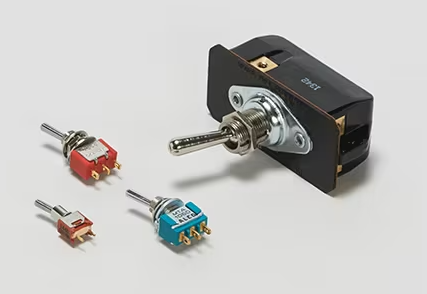
A toggle switch, also known as a slide switch, is a type of switch that can be toggled right to left or up and down. The on-off state of the circuit can be controlled by flipping the switch handle. Toggle switches are available in many types and specifications, including single pole single throw (SPST) and double pole single throw (DPST). High current ratings up to 5A and an epoxy seal make it excellent in high-current applications. Its terminal forms are diverse, and the contact material is silver plated and gold plated, so in practical applications, there are more subdivisions.
Detailed steps: how to wire a toggle switch
In this section, a detailed step-by-step guide of how to wire a toggle switch will be discussed, hoping this guide could help you quickly master this skill.
Preparation of tools for wiring a toggle switch
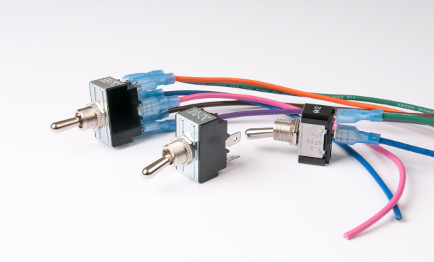
Before the major process of how to wire a toggle switch, you need to prepare some necessary tools and materials required for proper connection. There are different types of toggle switches, such as single pole single throw (SPST), single pole double throw (SPDT), etc., to choose according to your circuit needs.
Certainly, you also need some wire, and please make sure the wire thickness can suit your circuit current carrying requirements. Generally speaking, for small current circuits, thinner wires can be used; If it is a high-current circuit, choose a thicker wire instead.
In addition, a pair of wire strippers is essential, for it is used to strip the insulated outer skin of the wire to reveal the metal wire inside. If you are connecting toggle switches to the circuit board, you may also need welding tools such as soldering irons, solder wires, etc.
And remember this important CHECKS: check the toggle switch model, specifications, and rated voltage. Then check whether the wiring terminals and leads are intact. Replace them if they are damaged. According to the circuit design scheme, determine the installation position and fixing mode of the toggle switch.
Identification of the pin of the toggle switch
As there are mainly two common types of toggle switch, you just have to recognize the number of the pins. For single-pole single-throw (SPST) toggle switches, there are usually two pins. One is the input and the other is the output. When the toggle switch is in one position, the circuit is on; In another position, the circuit is disconnected.
As for single pole double throw (SPDT) toggle switches, they have three pins. The middle pin is usually the common end, and the other two pins are two different connected ends. Depending on the position of the toggle switch, the common end can be connected to one of the connecting ends.
Connection of the wire to toggle switch
And after recognizing which type of the toggle switch we are faced with, we come to the major assembly process of how to wire a toggle switch.
To begin with, use wire strippers to peel off one end of the wire, exposing about 0.5-1 cm of metal wire. If it is directly connected to the terminals of other wires or devices, wrap the exposed metal wires around the corresponding terminals and tighten them with screws to ensure secure connections. If it is connected to the pin of the toggle switch, for toggle switches without welding requirements, the lead can be inserted into the pin hole and then gently bent over the pin to secure the lead in the pin. If welding is required, preheat the soldering iron, then apply a small amount of solder to the pins and wires, align the wires with the pins, and heat the iron to melt the solder, welding the two together.
As for the two types of toggle switch, the wiring steps differ in some aspects. In order to show it more clearly, you can see the table below to find the answer you need.
|
Two ways of how to wire a toggle switch |
|
|
Single pole single throw (SPST) toggle switch wiring |
Step 1: Connect the positive terminal of the power supply to the input of the toggle switch. |
|
Step 2: Connect the output end of the switch to the load or ground end. |
|
|
Step 3: Test the working status of the toggle switch to ensure that the switch can be switched normally. |
|
|
Bipolar single throw (DPST) toggle switch wiring |
Step 1: Connect the positive terminal of the power supply to each of the two inputs. |
|
Step 2: Connect the two outputs of the switch to the two load or ground terminals respectively. |
|
|
Step 3: Test the working status of the toggle switch to ensure that the switch can control the on-off status of two circuits at the same time. |
|
Test connection of a toggle switch
Then we will come to the test of checking whether we have succeeded in wiring the toggle switch.
First, perform a visual inspection to ensure that the switches are installed correctly and that all connections are secure. Check that the pin of the switch is inserted correctly into the corresponding slot and is not loosen or bent.
Second, use a test tool, such as a multimeter or voltmeter, to test the wiring of the switch. Connect one end of the test tool to one wiring screw of the switch and the other end to the other wiring screws in turn. If the test tool makes a sound or shows a current passing through, the cable connection is correct. If there is no response, it may indicate a wiring error. If you choose to use a multimeter to test the connectivity of the circuit when it is safe to do so (such as connecting to a low-voltage circuit). Set the multimeter to resistance measurement. If it is a single-pole single-throw switch, the multimeter should display a smaller resistance value when the switch is on. When the switch is in the off position, infinite resistance should be displayed. For single-pole double-throw switches, it is also possible to test the connectivity between the common end and different connections by switching the switch position.
Third, you can also observe the status of the switch to determine whether the connection is wrong. For ordinary single-control switches, the switch should be connected by two wiring screws when the switch is closed, and the two wiring screws should be disconnected when the switch is opened. If the opposite is observed, the switch is connected incorrectly.
Where safe, test the function of the circuit. For example, if a toggle switch is used to control a light, when the switch is turned on and off, the light should turn on and off accordingly. If the light does not behave as expected, it may mean that the switch is not connected correctly. Or if there are circuit diagrams or switch instructions, you can refer to them to confirm the correct wiring mode. The circuit diagram usually indicates the function and connection mode of each pin.
Cautions of how to wire a toggle switch
When wiring a toggle switch, you need to pay attention to the following points to ensure safety and correct connection.
Proper installation: Toggle switches need to be properly installed to ensure that they work well with other electronics and achieve the desired circuit function. During installation, the pin of the switch needs to be connected to other devices and fixed in the appropriate position.
Avoid overload: When using toggle switches, it is necessary to avoid overload, so as not to damage switches or other circuit components. If you need to control high-power appliances, you can choose a switch with a larger rated current to improve its carrying capacity.
Vibration prevention: Toggle switches need to be protected from excessive mechanical vibration, so as not to affect their normal work and reduce the service life. During installation, ensure that the switch is stable and fixed, and take other appropriate measures, such as adding padding or installing supports.
Prevention of pollution: When using the toggle switch, attention should be paid to preventing pollution and corrosion to ensure its normal operation. Appropriate protective measures can be taken, such as installing a dust or waterproof cover, and the switch can be cleaned and maintained regularly.
Welding precautions: If you need to weld the toggle switch, you need to pay attention to the following points. When welding terminals, load is applied to the terminals to loosen, deform, and reduce electrical characteristics according to different conditions. Avoid using water-soluble flux because it may corrode the switch during welding. Set welding conditions based on actual batch production conditions. Do not allow flux to flow from around the printed circuit board to the switch. When soldering twice, please return to normal temperature after the first welding part. If continuous heating, it may deform the periphery, loosen the terminals, fall off, and reduce the electrical characteristics.
Regular inspection: Regularly check whether the wire connection of the switch is firm to prevent circuit failure caused by poor contact. Especially in humid, high temperature or high vibration environments, the frequency of checking the switch should be higher.
Final Verdict
Correctly wiring toggle switches requires careful identification of pins, selection of appropriate tools and materials, and accurate connection operations. With this step-by-step guide, hope you can successfully connect the toggle switch to your circuit to achieve the control function you need.

Disclaimer: The views and opinions expressed by individual authors or forum participants on this website do not represent the views and opinions of Chipsmall, nor do they represent Chipsmall's official policy.

share this blog to:


