


OUTLINE:
To Recognize Thermistor Symbol Easily
 352
352Thermistors, those versatile temperature-sensitive resistors, play a crucial role in various electronic circuits. But how are they represented on schematics? This guide delves into the world of thermistor symbols, equipping you to decipher them with ease.
Thermistors and Thermistor Symbols
Thermistors are a type of sensitive component. A thermistor is distinguished by its temperature sensitivity, which results in varying resistance levels at different temperatures. They are classified into positive temperature coefficient thermistors (PTC) and negative temperature coefficient thermistors (NTC) based on their temperature coefficient.
Specifications
- High sensitivity, its resistance temperature coefficient is 10 to 100 times greater than that of metal, and it can sense temperature fluctuations of 10-6 degrees Celsius.
- Normal temperature devices are suited for -55 °C to 315 °C, while high-temperature devices are acceptable for temperatures up to 2000 °C. Low-temperature devices are suitable for -273 °C to -55 °C.
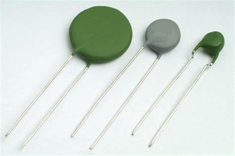
- Small volume, can measure the temperature of voids, cavities, and blood arteries in the live organism, which conventional thermometers cannot measure.
Thermistor symbols are graphic representations of thermistor components in electronics schematics. In rare circumstances, the precise kind of thermistor may be provided beside the symbol for more clarity, particularly if the component packaging style is critical to the application.
Key Aspects Of Thermistors:
1. Working Principle
·Thermistors are typically made of metal oxides or doped semiconductors.
·As the temperature increases, the vibrations of atoms within the material intensify.
·This increased vibration disrupts the flow of electrons, increasing the resistance in Positive Temperature Coefficient (PTC) thermistors.
·Conversely, in Negative Temperature Coefficient (NTC) thermistors, the increased vibration improves the flthermistor symbol
ow of electrons, leading to a decrease in resistance with rising temperature.
2. Types Of Thermistors
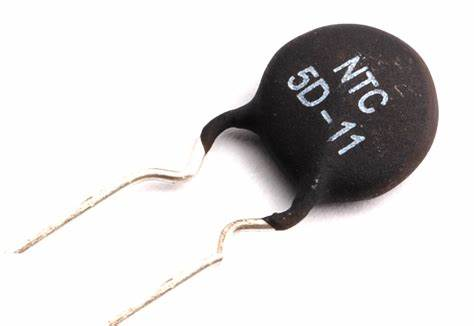
NTC Thermistors: A more common type, exhibiting a decrease in resistance with increasing temperature.
-
Material: Made from semiconductor materials like metal oxides (e.g., manganese, nickel, cobalt oxides).
-
Resistance vs. Temperature: As the temperature rises, the vibration of atoms within the NTC thermistor increases. This vibration disrupts the flow of electrons, leading to a decrease in resistance. This change in resistance is predictable and can be used to measure temperature.
PTC Thermistors: Less common, showing an increase in resistance with rising temperature.
-
Material: Made from semiconducting materials or doped polymers that exhibit a unique resistance-temperature relationship.
-
Resistance vs. Temperature: As the temperature increases in a PTC thermistor, the material properties change. The movement and interaction of electrons become restricted, leading to a sharp rise in resistance. This change can be dramatic and even exponential beyond a certain threshold temperature.
Thermistor Symbols:
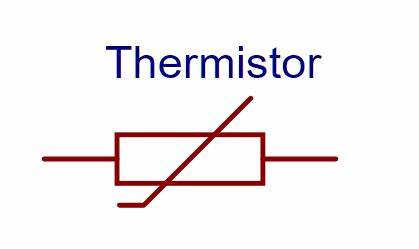
1.The Basic Thermistor Symbol
The fundamental thermistor symbol consists of two main elements:
Resistor Symbol: This resembles a zigzag line representing the resistive element.
Temperature-Dependent Curve: A short, curved line is positioned either above or below the resistor symbol.
2.Interpreting the Curve
The position of the curve relative to the resistor symbol indicates the type of thermistor:
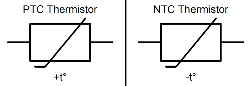
·Positive Temperature Coefficient (PTC): The curve is positioned above the resistor symbol. As temperature increases, the resistance of a PTC thermistor also increases.
·Negative Temperature Coefficient (NTC): The curve is positioned below the resistor symbol. As temperature rises, the resistance of an NTC thermistor decreases.
The Applications of Thermistor Symbols
While thermistors themselves have numerous applications, the thermistor symbol serves a specific purpose within the realm of electronics:
1. Schematic Representation:
·The primary function of a thermistor symbol is to visually represent the actual thermistor component in an electronic schematic. This enables engineers and technicians to:
-
Identify the presence and location of thermistors within the circuit.
-
Gain a basic understanding of the thermistor's type (NTC or PTC) based on the position of the curve relative to the resistor symbol.
·By incorporating thermistor symbols into schematics, engineers can create clear and concise diagrams that effectively communicate the circuit's design and functionality.
2. Communication and Documentation:
·Thermistor symbols play a crucial role in facilitating clear communication between engineers and other electronics professionals working on the same project.
·The standardized nature of the symbol ensures everyone involved can unambiguously understand the presence and type of thermistors in the circuit, regardless of individual drawing styles or language barriers.
·This standardization promotes consistent documentation and simplifies the process of:
Reviewing schematics for clarity and accuracy.
Troubleshooting potential circuit malfunctions.
Modifying circuit designs for improvement or adaptation.
Advantages and Limitations
Thermistor symbols, despite their simplicity, offer several advantages and limitations in the realm of electronics:
Advantages:
·Clear and Concise Communication: The standardized symbol allows engineers and technicians to unequivocally understand the presence and nature of thermistors within a circuit, regardless of language barriers or individual drawing styles. This facilitates efficient communication and collaboration.
·Efficient Schematic Representation: The symbol acts as a visual shorthand, conveying the essential information about the thermistor (NTC or PTC) in a compact and easily recognizable format. This reduces clutter and improves the readability of complex schematics.
·Universally Recognized: Standardization ensures the symbol is understood by professionals globally, fostering consistency in documentation and simplifying the process of reviewing, troubleshooting, and modifying electronic circuits across different teams and companies.
·Additional Information Potential: While not always employed, the symbol can sometimes incorporate letters or numbers to convey specific thermistor characteristics or model information, providing additional context for the component's functionality.
Limitations:
·Limited Detail: The symbol primarily focuses on conveying the basic type of thermistor (NTC or PTC) and lacks the ability to represent more intricate details like specific resistance values, temperature range, or other technical specifications. This information needs to be provided elsewhere in the schematics or component lists.
·Overreliance on Standardization: While standardization has its benefits, it can also limit the symbol's potential to represent more complex thermistor types or custom variations. In such cases, additional annotations or explanations might be necessary to ensure clarity.
Final Verdict
In conclusion, thermistors are versatile components that play a significant role in various temperature-related applications. Understanding their working principles, types, and applications equips you to appreciate their valuable contribution in diverse fields. And understanding the thermistor symbols will help you read the diagram easier.
Disclaimer: The views and opinions expressed by individual authors or forum participants on this website do not represent the views and opinions of Chipsmall, nor do they represent Chipsmall's official policy.

share this blog to: