OUTLINE:
A Thorough Explanation of Wiring Diagram of Relay
 576
576By understanding relay wiring diagrams, you gain valuable insight into how relays function and control circuits. This knowledge can be helpful for various electrical projects.
What Is a Wiring Diagram of Relay
A relay wiring diagram visually represents how a relay is connected within a circuit. It illustrates the connections between the relay's coil, contacts, power source, and the controlled device.
Components in a Relay Wiring Diagram:
-
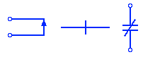
Coil:Represented by a rectangle with a straight line in the middle, often labeled with a "coil voltage" value (e.g.12V).
Contacts: Shown as lines or shapes representing the switching mechanism. Common symbols include:
-
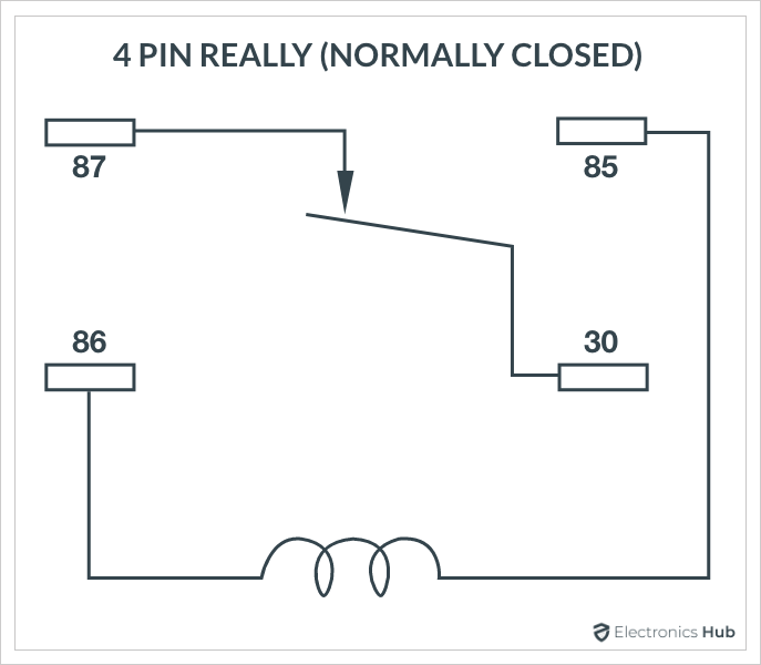
COM (Common):The central contact that connects to either NO or NC depending on the relay state.
-
NO (Normally Open):The contact that is open when the coil is not energized and connects to COM when the coil is energized.

-
NC (Normally Closed):The contact that is closed when the coil is not energized and disconnects from COM when the coil is energized.

-
Changeover Contact: This is the changeover contact of a relay that is closed or connected with one terminal (known as normally closed terminal) when the relay is deactivated & the other terminal is open (known as normally open terminal). It changes the contact’s position when the relay activates.

-
Open Contacts:These are the symbols used for representing the open contacts of a relay. It means the contact is break & there is no flow of current.

-
Closed Contacts:These symbols represent closed contacts or make contact. The contacts are short & the current can flow through it.
-
Power Source: Represented by a battery symbol (+) (-) for DC voltage or a sine wave for AC voltage.
-
Controlled Device: Symbolized depending on the device (e.g., light bulb, motor).
Each relay has a name. Generally, the normally open point and the normally closed point share the same name with the relay.
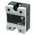
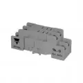
If there are 10 relays, there will be 10 names. Just make sure that each relay and contact is not confused with other relays. Here is the wiring diagram of a small solid state relay
.webp)
Types of Wiring Diagram of Relay:
There are various relay wiring diagrams depending on the specific function and type of relay. Here are two common examples:
-
SPDT Relay (Single Pole Double Throw): This has one input (COM), one control coil, and two outputs (NO and NC). The diagram shows how the COM connects to either NO or NC depending on the coil state.
-
Simple SPST Relay (Single Pole Single Throw): This has one set of contacts (COM and NO) and one control coil. The diagram shows how the COM connects to NO when the coil is energized, completing the circuit for the controlled device.
What Is The Wiring Diagram Of Relay Used For
Relay wiring diagrams are like blueprints for connecting a relay within a circuit. They visually represent how the relay's coil, contacts, power source, and the device being controlled are all interconnected.
Purpose of Relay Wiring Diagrams:
-
Clear Instructions: Relay wiring diagrams provide a step-by-step visual guide on how to connect the various components of a relay circuit. They show the proper connections between the coil, contacts, power source, and the device you want to control.
-
Universal Understanding: Electrical engineers and technicians worldwide rely on standardized symbols in these diagrams. This ensures everyone interpreting the diagram understands the functionality regardless of language barriers.
-
Reduced Errors: Following a clear wiring diagram significantly reduces the risk of mistakes during circuit assembly. This promotes electrical safety and ensures the circuit functions as intended.
Common Applications of Relay Wiring Diagrams:
-
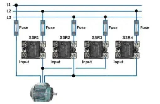
Automotive Applications:Relays are extensively used in cars for controlling headlights, windshield wipers, power windows, and other features. Wiring diagrams are crucial for proper installation and repair of these systems.
-
Home Automation Systems:Relays play a role in smart home devices, controlling lights, thermostats, and security systems. Wiring diagrams ensure correct connections for these automated functions.

-
Industrial Control Systems:Factories and industrial plants heavily rely on relays for automating machinery and processes. Precise wiring diagrams are essential for safe and efficient operation of these systems.

-
DIY Electronics Projects:Hobbyists use relays in various projects. Wiring diagrams guide them on how to connect the relay to control lights, motors, or other electronic components.
How To Read Relay Circuit Diagram
-
Identify the Power Source: Locate the battery symbol (+) (-) for DC or sine wave for AC, representing the voltage that will energize the coil.
-
Trace the Control Circuit: Follow the path from the power source, through any control components (switches, resistors, logic gates) that might trigger the relay coil.
-
Coil Activation: When the control circuit allows current to flow through the coil, the relay is activated.
-
Contact Switching: Depending on the relay type (SPDT, DPDT, etc.), the contacts will switch based on the energized coil.
-
SPDT: COM will connect to either NO or NC.
-
DPDT: Two sets of contacts (COM, NO, NC) will switch independently based on the coil.
-
-
Controlled Device: The switched contacts (COM and NO/NC) will then complete the circuit for the device being controlled (motor, light, etc.).
Tips for Easier Reading:
-
Color Coding: Some diagrams might use color coding to differentiate between control circuits, power supply, and the controlled device.
-
Voltage Labels: Pay attention to voltage labels on the coil and power source to ensure compatibility.
-
Relay Type: Identify the relay type (SPDT, DPDT) based on the number and arrangement of contacts.
Conditions Where Wiring Diagrams Of Relays Are Used
Here are some common conditions where wiring diagrams of relays are used:
Controlling Higher Current or Voltage Devices:
-
Low-power control of high-power circuits: Relays are often used because a small control signal from a microcontroller or low-power switch can activate the relay coil, which then controls a much higher current or voltage for powering devices like motors, lamps, or heaters. The wiring diagram will show the low-power control circuit connected to the coil, and the high-power device connected to the relay contacts.
Isolation and Protection of Control Circuits:
-
Separating sensitive control circuits from high-power lines: Relays can isolate the control circuit from the high-power circuit being controlled. This protects the delicate control circuitry from voltage spikes or surges that might occur in the power circuit. The wiring diagram will show the control circuit connected to the coil, and the power circuit completely separate but controlled by the relay contacts.
Logic Control and Automation:
-
Creating complex control systems with multiple relays: By combining relays with logic gates or other control circuits, you can design automated systems that respond to specific conditions. The wiring diagram will show the control logic connected to the relay coils, and the various devices being controlled by the relay contacts based on the control signals.
Safety Interlocks:
-
Ensuring safe operation of machinery or processes: Relays can be used to implement safety interlocks that prevent a machine from operating until certain safety conditions are met. The wiring diagram will show the safety sensors connected to the control circuit, which in turn controls the relay coil. The relay contacts might then control power to the machine or other safety-critical functions.
Conclusion
In essence, wiring diagrams of relay are fundamental tools for understanding, building, and maintaining circuits that utilize relays. They provide a clear visual language for electrical communication, ensuring safe and effective operation of relay-controlled systems.
Disclaimer: The views and opinions expressed by individual authors or forum participants on this website do not represent the views and opinions of Chipsmall, nor do they represent Chipsmall's official policy.

share this blog to: